Light Sensor
The light sensor array presented here was designed to be an educational instrument for use in the Galapagos Islands. The island chain experiences a multitude of problems - from invasive species to overfishing to saline soil to a lack of educational resources. This project was intended to solve two problems simultaneously: provide a technologically based educational device for use in cataloging invasive species effects.
The design
Using Adobe Illustrator and a laser cutter, I developed the dimensions for each of the three layers: two 3/4" plywood pieces, and one 1/4" acrylic layer. The colors in the neighboring figure represent the various layers, with all being cut to a 12" diameter circle visualized by the green circle. The lower plywood layer is blue, the upper plywood layer is red and blue, and the acrylic layer is in green.
Using the laser cutter, I etched both of the plywood layers with their respective cut lines, then conducted multiple passes on the 1/4" acrylic to cut out all elements.
the build
Using a jigsaw, router, and vertical belt sander, I used the lines etched by the laser cutter to finish the plywood layers. The bottom layer was plunge routed to produce the center cut out where the electronics were housed, and rough cut to circular using a jigsaw. Finally, the circle was belt sanded to a finished edge and assembly holes were drilled.
The top plywood layer was again rough cut to circular using a jig saw and sanded to finish. The center cut out was rough cut using a jigsaw and finished with a straight bit router. The arm lines were cut with a jigsaw, and assembly holes were again drilled.
the assembly
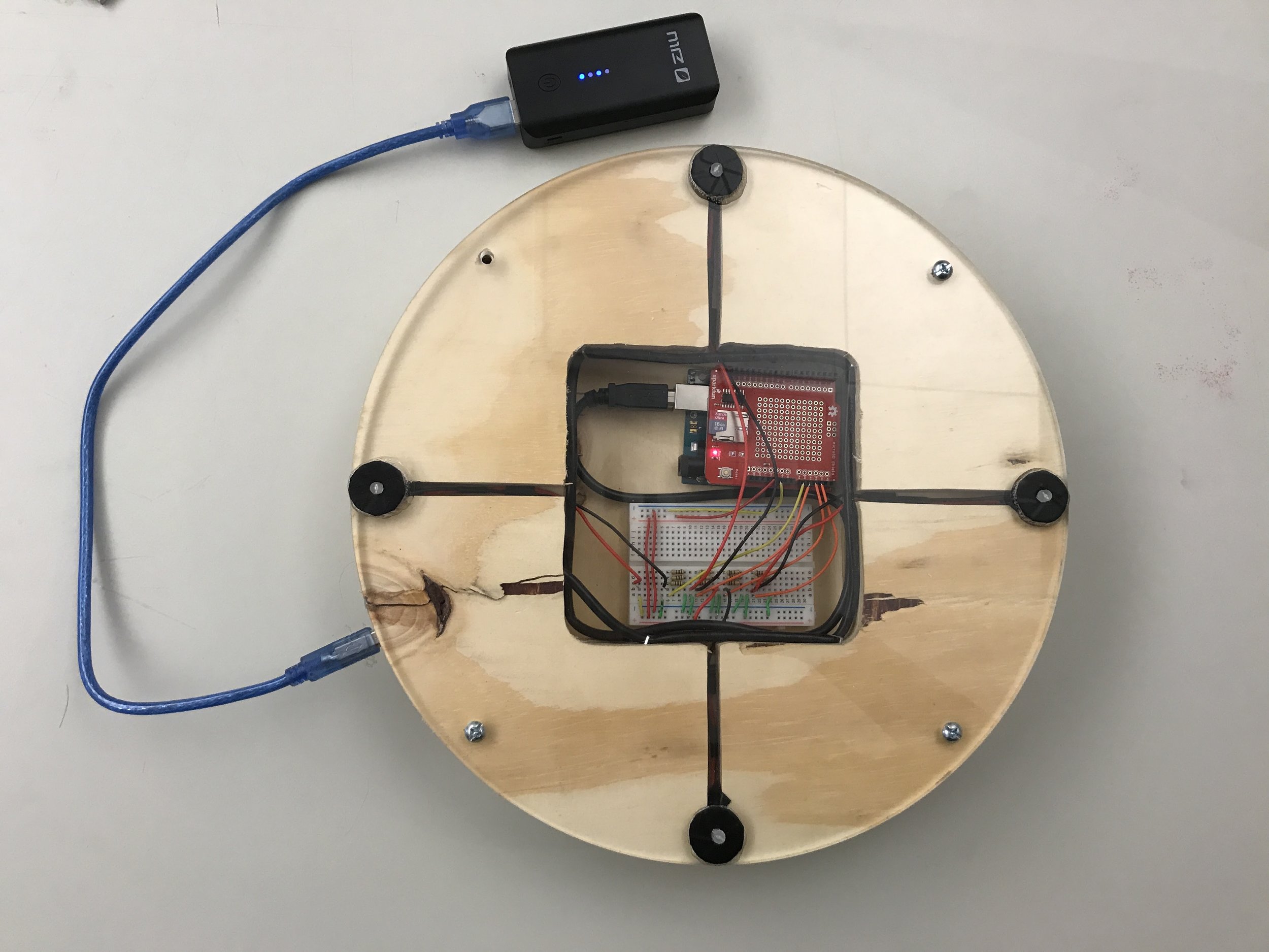
The electronics needed power and data access, as the device was designed to be closed to user interaction. We designed it to be closed for the fact that Arduino knowledge on the island is decidedly limited, and if it were disassembled it would likely never be reassembled. I used a router to trough cut the upper plywood layer with a straight bit to attach the power and data line, and then wound the extra wiring inside the housing.
The Arduino, SD shield, and protoboard were mounted on the bottom layer, and the light sensors were mounted on the face of the acrylic layer with wire extensions.
With the data wire wrapped, the Arduino, SD shield, and protoboard mounted, the device was almost finished. On the acyrlic layer, the light sensors were mounted to holes aligned with the arm lines in the plywood layer, with jumper wires soldered to both anode and cathode.
To keep the overall aesthetic of the device, the jumper wires between the protoboard and the light sensors had to be kept as short as possible. As such, the only access to attach the wires was between the two plywood layers, using needle nose pliers. I cut the wires to length, stripped the ends, and one by one inserted them to their respective lines on the protoboard through the 1.5 inch gap shown in the neighboring photo.
the Final product
The build came together nicely, and the battery pack we provided could power the device for 100 hours. With a 64GB SD card, the device was ready to collect data for over four days unattended. I wrote the code to take light data every 15 minutes, average it from each sensor, and save it to the SD card. I also developed the code to download the data from the device after collection, and to clear the card after downloading.

